
Start a Project
What we do
Capabilities Services Industries
Work
Company
About Careers Contact
Start a Project
Selected work 07

An autonomous vision and motion system for commercial vehicle capture.

The client identified commercial vehicles from the roadside using photographers with long lenses, panning by hand. We engineered the system that replaced them, covering detection, speed estimation, camera motion and capture, and delivered a working unit that now runs unattended.
Client
Vehicle data operator, Singapore
Industry
Computer vision & intelligent systems
Stage at start
Concept
Volvix Systems role
Detection, timing, motion control and capture software
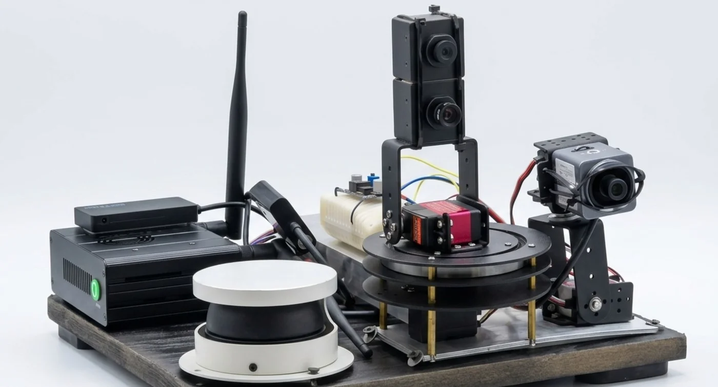
The development rig: a scanning rangefinder, an embedded computer and three cameras, two of them on a driven rotating stage
DEVELOPMENT RIG — THE BENCH SYSTEM THE CONTROL SOFTWARE WAS BUILT AND TUNED AGAINST
01 / The brief

The client collects identification data on commercial vehicles from the roadside in Singapore. The work was done by DSLR photographers: standing beside an expressway with long lenses, tracking each vehicle by hand as it passed, and capturing both the licence plate and the operator marking on the vehicle’s side within the same pass.

The method produced usable results but did not scale. A photographer holds the task for around three hours before accuracy falls away, and every hour of coverage costs an hour of someone’s attention. The client specified a unit that could be mounted at the roadside and left to run.

The defining requirement was timing. Two of the three photographs are taken from a single rotating axis that has to be square to the vehicle at the moment it passes, and the rate that axis must turn differs for every vehicle.

02 / The problem

A person panning a camera matches the vehicle by eye. The system does it by measurement, continuously, as the vehicle approaches.

Three photographs have to be taken of the same vehicle while it travels past at expressway speed. One is straightforward: a fixed long lens on the licence plate, fired as the vehicle crosses a known line. The other two are not. They sit on a single rotating axis that has to be square to the side of the vehicle at the instant the vehicle is beside it, and the target on that side, a marking near the front wheel, is only a few hundred millimetres wide.

The required rotation rate is not a constant. It is a function of the vehicle’s speed and its distance from the unit, and neither is known until the vehicle is already inside the measured area. A vehicle in the near lane needs the axis turning faster than the same vehicle further out. Get the rate wrong and the marking leaves the frame. Start the rotation at the wrong moment and it never enters it. The environment is uncontrolled: a closely followed vehicle places a second object inside the same measured area, and reacting to the wrong one photographs the wrong vehicle.

The rotation also has to continue through the exposure. This is what a photographer does when following a moving subject: while the camera tracks at the subject’s angular rate, the subject stays sharp at a shutter speed that would otherwise blur it. Halting the axis for the exposure removes that benefit and returns the motion to the image, so capture occurs mid-travel and the axis continues past it before resetting. Every camera on the array is global shutter, so the whole frame is exposed at one instant and a vehicle at speed is recorded without geometric skew.
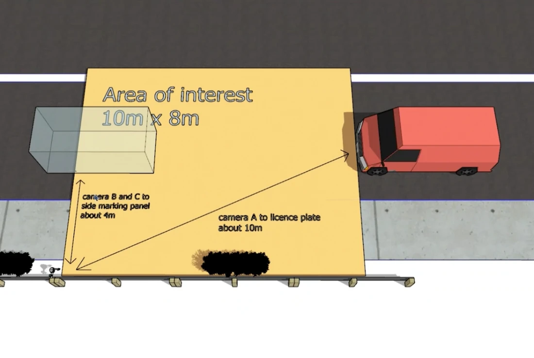
Plan view of the area of interest beside the carriageway, 10 m by 8 m, with the licence plate camera about 10 m from the vehicle and the side cameras about 4 m from the side marking panel
Area of interest
A measured rectangle beside the carriageway, and only the nearest point inside it.
Detection is bounded to a defined ground rectangle, 10 m along the carriageway by 8 m across it. Within that rectangle the system follows a single point, the leading edge of the closest vehicle, and ignores everything behind it. The plate is photographed at about 10 m. The side cameras work at about 4 m from the marking panel.
03 / What we did

Hardware selection and the physical arrangement were the client’s. We engineered everything that makes the arrangement behave as an instrument: what it watches, when it decides, how fast it moves, and what it keeps.

01Detection & tracking — Scanning range data is reduced to a bounded ground rectangle beside the unit and, within it, to the single nearest approaching point. A following vehicle cannot displace the one being measured, and objects outside the rectangle never enter the decision at all. 02Speed estimation & triggering — Approach speed is derived as the tracked point crosses the far edge of the rectangle, early enough to be useful. The plate camera fires at a configured distance, and the vehicle’s lateral offset is recorded at the same instant, since every later decision depends on it. 03Panning control — The bearing of the tracked vehicle is followed in real time, and the camera arm is driven to match its angular rate as it approaches, so the axis and the vehicle arrive square to each other. Travel is constrained to ±45° from position feedback, and the axis returns to its default heading and re-arms as soon as the pass completes. 04Capture & camera control — The two moving cameras are released on reported axis position rather than on elapsed time, so framing does not drift with supply voltage or mechanical wear. The axis is not halted for the exposure. It runs through it and past it, which is what keeps a moving subject sharp without demanding an impractically short shutter. Exposure and gain are held under software control per camera, across a monochrome sensor for the plate and colour sensors for the vehicle side, for the same reason and for poor light. 05Record assembly & filtering — The three frames are combined into a single sequentially numbered, timestamped record. Records that do not match the vehicle classes the client is looking for are discarded on the unit, and a running count of records taken against records discarded is kept for every session. 06Field configuration — Everything an installer needs to tune on site is exposed as a parameter: trigger distance, exposure and gain per camera, a scaling coefficient on the panning rate, and independent trigger offsets for the two moving cameras. The unit is reachable over a wireless link so cameras can be aimed and framing checked from a laptop at the roadside.
04 / Where it stands

Work done by hand at the roadside, now carried out by an unattended unit.

Before
Photographers panning long lenses by hand, one vehicle at a time, for no more than about three hours at a stretch.
After
An unattended unit that detects, times its own motion, captures three frames and keeps only the records that qualify.
Next
Delivered and in use, in the client’s own weather-resistant housing. Night operation would require synchronised illumination.

Have a system that has to work outside the lab?

Tell us what you are working on and what you need help with.

Start a Project